
Prekių nėra
(Kainos su PVM)
 Padidinti

Tik internetu
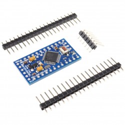
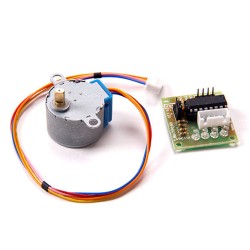
Valdiklis su ULN2003
d0125
Nauja prekė
Šis Arduino modulis yra skirtas situacijoms, kur Arduino turi valdyti didesnės galios elektroniką (pvz. variklius, reles). Gali valdyti iki 7 kanalų. Išėjimai prijungti arba prie 0V (įjungta) arba trečiojoje būsenoje (išjungta), taigi šis modulis netinkamas dvikrypčiams nuolatinės srovės varikliams valdyti. Tačiau tinkamas žingsniniams varikliams valdyti.
Prekių kiekis mūsų sandėlyje: 84
Charakteristikos
| Suderinama su Arduino™ ir *duino | Taip |
| Kanalų skaičius | 7 |
| Maksimali valdoma srovė | 500 mA kanalui |
| Maksimali valdoma įtampa | 12V (DC) |
| Būsenos indikacija | Taip. LED |
| Maitinimo įtampa | 3-12V (DC) |
| Maksimali maitinimo įtampa | 15V (DC) |
| Jungties žingsnis | 2,54mm |
| Jungties tipas | Male (vyr.) |
| Kontaktų kiekis | 21 |
| Matmenys | 41 x 21 mm |
| Naudojami mikrovaldiklio prievadai | iki 7 skaitmeninių I/O |
| Pagrindinės funkcijos grandynas | ULN2003 |
| Išėjimo įtampa | 0V arba neapibrėžta (neprijungta) |
Apie prekę
Description
The Mini Stepper Driver is small size and easy to use. It used ULN2003 to amplify the control signal from the Arduino. The Drive voltage can up to 15v.
Features
- The most easy module to learn how to control the Stepper and finish the simple project.
- The logic control voltage:3~5.5V
- Motor Supply Voltage: 5~ 15V
- it can sink 500mA from a 50V supply,but you'd better limit the driver voltage under 15v.
- Operating temperature: -25 degree Celsius ~ +90 degree Celsius
HOW TO CONTROL STEPPER
Step motor is to a machine to convert pulse to angle displacement. So if you give stepper driver a certain pulse signal, it will drive step motor to a certain angle. you can control the angle the stepper moved by the number of the pulse. And you also can control the speed of the stepper rotate by the frequency of the pulse. The following picture is the schematic of the stepper driver.

The following picture is the control signal to drive a 28BYJ48 stepper to rotate 1/4096 circle.
| line | 1 | 2 | 3 | 4 | 5 | 6 | 7 | 8 |
|---|---|---|---|---|---|---|---|---|
| red | 1 | 1 | 1 | 1 | 1 | 1 | 1 | 1 |
| orange | 1 | 1 | 0 | 0 | 0 | 0 | 0 | 1 |
| yellow | 0 | 1 | 1 | 1 | 0 | 0 | 0 | 0 |
| pink | 0 | 0 | 0 | 1 | 1 | 1 | 0 | 0 |
| blue | 0 | 0 | 0 | 0 | 0 | 1 | 1 | 1 |
So we defined the time series in a array
<br>byte CCW[8] = {0x09,0x01,0x03,0x02,0x06,0x04,0x0c,0x08};  //CouterClockWise
<br>byte CW[8]= {0x08,0x0c,0x04,0x06,0x02,0x03,0x01,0x09};    //ClockWise
and in the following usage it will run, and then you must know how to drive a stepper.
Program Arduino as following:
/***************************
This code is shared by elecrow.com
it is public domain, enjoy!
it is used to control 28BYJ stepper
it can be changed to control almost all the 4-wire or 5-wire stepper.
*************************/

/*
The time Series to control the stepper
--make your making more easy!
*/
byte CCW[8] = {0x09,0x01,0x03,0x02,0x06,0x04,0x0c,0x08};
byte CW[8] = {0x08,0x0c,0x04,0x06,0x02,0x03,0x01,0x09};

const int stop_key = 14;  //stop_button connect to Arduino-A0
byte  change_angle=64;  //change the parameter to change the angle of the stepper

void Motor_CCW()    //the steper move 360/64 angle at CouterClockwise
{
  for(int i = 0; i < 8; i++)

    for(int j = 0; j < 8; j++)
    {
     if(digitalRead(stop_key)==0)
      {
      PORTB =0xf0;
      break;
      }
      PORTB = CCW[j];
      delayMicroseconds(1150);
    }
}
void Motor_CW()  //the steper move 360/64 angle at Clockwise
{
  for(int i = 0; i < 8; i++)

    for(int j = 0; j < 8; j++)
    {
    if(digitalRead(stop_key)==0)
      {
      PORTB =0xf0;
      break;
      }
      PORTB = CW[j];
      delayMicroseconds(1150);
    }
}

void setup()
{
  pinMode(stop_key,INPUT);
  digitalWrite(stop_key,HIGH);
  Serial.begin(57600);
  DDRB=0xff;
  PORTB = 0xf0;
  for(int k=0;k<change_angle;k++)
  {
  Motor_CCW();
  }
 }

void loop()
{
 Motor_CCW();  //make the stepper to anticlockwise rotate
// Motor_LR(); //make the stepper to clockwise rotate
}
Atsiliepimai
Šiuo metu klientų atsiliepimų nėra.
Priedai


30 kitos prekės toje pačioje kategorijoje:
-
Valdomas žemo dažnio PWM signalo generatorius
9,93€
-

11 x 11 mm aušintuvas
0,58€
-
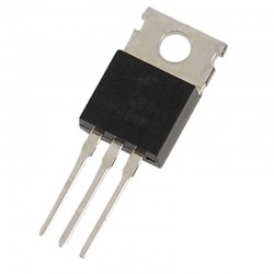
IRF520N tranzistorius
0,70€
-
4x IRF540N tranzistorių modulis
9,98€
-
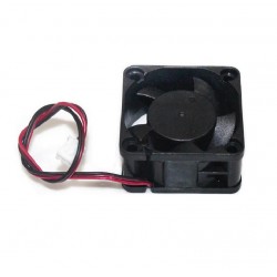
Aušintuvas 4020 12VDC
2,42€
-
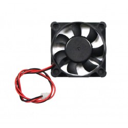
Aušintuvas 5010 12VDC
1,69€
-

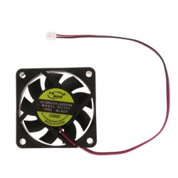
Aušintuvas 5010 5VDC
1,69€
-
Aušintuvas 6015 12VDC
2,54€
-
Aušintuvas 6015 5VDC
2,54€
-
Aušintuvas 6015 24VDC
2,54€
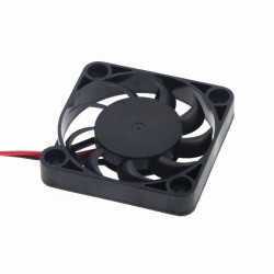
-
Aušintuvas 3010 12VDC
1,51€
-
Aušintuvas 6010 24VDC
3,00€
-
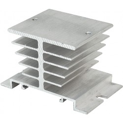
Aušintuvas SSR relėms tvirtinamas prie DIN bėgelio
4,82€
-
Aušintuvas 4007 12VDC
2,54€
-
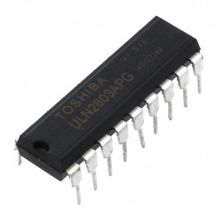
ULN2803 mikroschema (8 x 500mA darlington masyvas)
0,85€
-
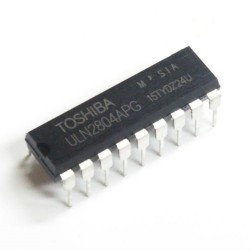
ULN2804 mikroschema (8 x 500mA darlington masyvas)
1,09€
-
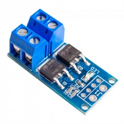
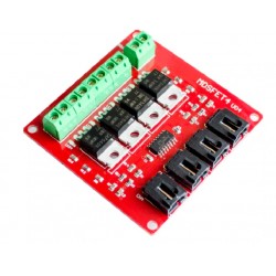
Mosfet tranzistorių modulis (15-30A) 400W
3,63€
-
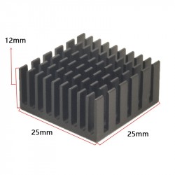
25 x 25 x 12 mm aušintuvas
0,97€
-
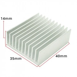
40 x 35 x 14 mm aušintuvas
1,94€
-
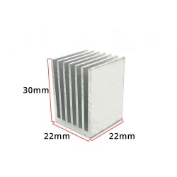
22 x 22 x 30 mm aušintuvas
1,69€
-
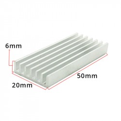
50 x 20 x 6 mm aušintuvas
0,97€
-
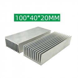
100 x 40 x 20 mm aušintuvas
7,33€
-
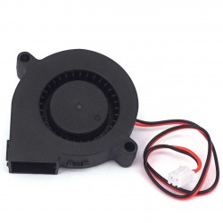
Turbinos tipo aušintuvas 5015 12VDC
3,63€
-
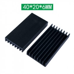
40 x 20 x 6 mm aušintuvas
1,21€
-
100 x 22 x 10 mm aušintuvas
2,03€
-
20 x 20 x 10 mm aušintuvas
0,97€
-
9 x 9 x 12 mm aušintuvas
0,85€
-
25 x 34 x 12 mm aušintuvas
0,97€
-
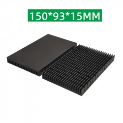
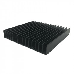
150 x 93 x 15 mm aušintuvas
22,47€
-
120 x 120 x 20 mm aušintuvas
18,62€