Prekių nėra
(Kainos su PVM)
")
")
")
")
Tik internetu
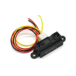
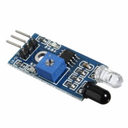
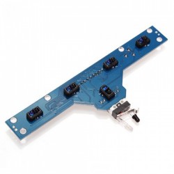
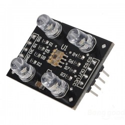
IR kliūties aptikimo modulis
d0071
Nauja prekė
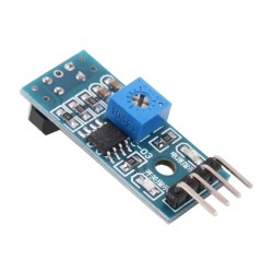
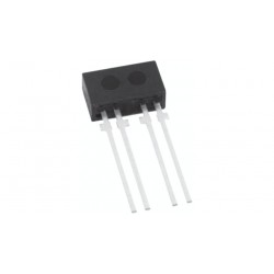
Šis atsispindinčių IR spindulių jutiklis (diffuse reflective sensor) gali būti naudojamas ne tik objektų aptikimui, tačiau ir kaip linijos sekimo modulis. Galima reguliuoti slenkstinę ribą. Naudojamas moduliuotas signalas, kurio dažnį galima šiek tiek reguliuoti siekiant geriausio efekto. Išėjimas aktyvus esant objektui.
Prekių kiekis mūsų sandėlyje: 81
Charakteristikos
| Suderinama su Arduino™ ir *duino | Taip |
| Būsenos indikacija | Taip. LED |
| Maitinimo įtampa | 3,3V arba 5V |
| Maksimali maitinimo įtampa | 5,5V |
| Dažnis | 38kHz |
| Jungties žingsnis | 2,54mm |
| Jungties tipas | Male (vyr.) |
| Kontaktų kiekis | 4 |
| Matmenys | 31 x 15 mm |
| Maksimali srovė | 16mA |
| Naudojami mikrovaldiklio prievadai | 1 skaitmeninis I/O |
| Pagrindinės funkcijos grandynas | LM393 |
| Darbinis atstumas | 20-300 mm (iki 35 laipsnių kampu) |
| Reguliuojamas jautrumas | Taip |
| Išėjimo tipas | Skaitmeninis |
Apie prekę
Specifications:
Working voltage: 3.3V to 5VDC
Working current: ≥ 20mA
Operating temperature: -10°C to +50°C
Detection distance: 2 to 40cm
IO Interface: 4-pin (EN / +V / S / GND)
Output signal: TTL level
LOW level pulse if obstacle is detected
HIGH if no obstacle detected
Adjustment: two single-turn variable resistors
Effective angle: ±35°
Size: 28mm × 23mm
Weight: 9g
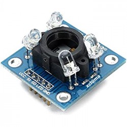
At the heart of the sensor is an NE555 chip configured to generate a 38kHz square wave. (The IR-08H uses an SN74LS00.) The 38kHz signal is used to illuminate an Infra Red (IR) LED. Light reflected from the LED is detected by a Vishay HS0038B IR receiver module (see data sheet). The receiver module incorporates an external, optical, 950nm IR filter and an internal, electronic, 38kHz band-pass filter that make the module receptive only to IR light pulsing at that frequency.
One of the potentiometers on the board (R6) is used to fine tune the signal to exactly 38kHz. The other (R5) adjusts the duty cycle of the signal, which controls the brightness of the IR LED.
Both adjustments together effect the sensitivity or range of the device. Proper adjustment of R6 requires an oscilloscope or a frequency counter. Otherwise it can be left centered or as it came from the manufacturer.
The receiver module also includes an AGC (Automatic Gain Control) that will suppress a continuous signal of any frequency, including 38kHz (see excerpt from data sheet, below). Therefore, it is absolutley necessary to use the 'EN' or 'Enable' pin for proper operation of the device. If the Enable function is used correctly, the device will achieve its maximum sensitivity.
On most versions of this device, the Infra Red (IR) LED is already covered with a small piece of black shrink tubing; but I find that additional optical shielding is required. A small cardboard tube commonly used as packing material will work satisfactorily, as will a variety of other materials.
When the GREEN JUMPER is installed on the board (see picture), the IR LED will flicker continuously at 38kHz. If the Enable (EN) function will not be used, the jumper must be installed . When the jumper is removed, pin 4 of the 555 timer is held LOW (RESET) by R3, a 22K pull-down resistor. Then, if a HIGH condition is applied to the EN pin, the reset condition will be relieved and the 555 timer will begin to oscillate. The Enable function cannot be used if the GREEN JUMPER is in place. You must remove the jumper on the board in order to use the EN (Enable) pin.
Sample C++ code to strobe the IR LED with a 600µs pulse and test for a return:
digitalWrite( enablePin, HIGH); // Enable the internal 38kHz signal.
microDelay( 210); // Wait 210µs (8 pulses of 38kHz).
if( digitalRead( outputPin)) // If detector Output is HIGH,
{
objectDetect = false; // then no object was detected;
}
else // but if the Output is LOW,
{
microDelay( 395); // wait for another 15 pulses.
if( digitalRead( outputPin)) // If the Output is now HIGH,
{ // then first Read was noise
objectDetect = false; // and no object was detected;
}
else // but if the Output is still LOW,
{
objectDetect = true; // then an object was truly detected.
}
}
digitalWrite( enablePin, LOW); // Disable the internal 38kHz signal.
From the HS0038BD data sheet:
These products are designed to suppress spurious output pulses due to noise or disturbance signals. Data and disturbance signals can be distinguished by the devices according to:
carrier frequency,
burst length and
envelope duty cycle.
The data signal should be close to the band-pass center frequency of 38 kHz and fulfill the following conditions. After each burst of 10 to 70 cycles, a minimum gap time in the data stream of 10 cycles is needed. For bursts greater than 70 cycles, a minimum gap time in the data stream of greater than 4x the burst length is needed. When a data signal is applied to the IR receiver in the presence of a disturbance signal, the sensitivity of the receiver is reduced to insure that no spurious pulses are present at the output. Some examples of disturbance signals which are suppressed are:
DC light (e.g. from tungsten bulb or sunlight)
Continuous signals at any frequency
Strongly or weakly modulated noise from fluorescent lamps with electronic ballasts.
Atsiliepimai
Šiuo metu klientų atsiliepimų nėra.
Priedai


20 kitos prekės toje pačioje kategorijoje:
-
IR kliūties aptikimo modulis (linijos sekimo) su TCRT5000
2,08€
-
Spalvos atpažinimo modulis su TCS3200
7,79€
-
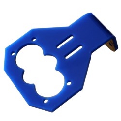
Ultragarsinio jutiklio laikiklis (storesnis žemesnis)
3,12€
-
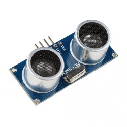
Ultragarsinis atstumo matavimo modulis HC-SR04
2,12€
-
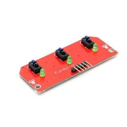
IR linijos sekimo modulis (3 kanalų) su TCRT5000
7,26€
-
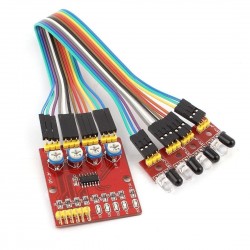
IR refleksinis priartėjimo modulis (4 kanalų)
4,72€
-
IR kliūties aptikimo modulis (linijos sekimo)
1,48€
-
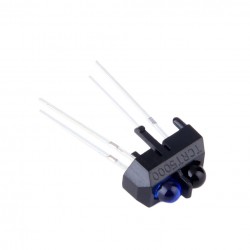
Refleksinis IR kliūties aptikimo (linijos sekimo) jutiklis TCRT5000
0,79€
-
IR linijos sekimo modulis (5 kanalų) su TCRT5000
12,49€
-
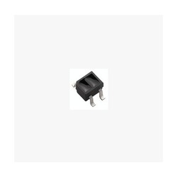
Refleksinis IR kliūties aptikimo (linijos sekimo) jutiklis ITR8307
0,73€
-
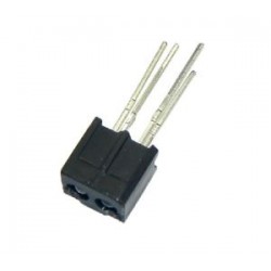
Refleksinis IR kliūties aptikimo (linijos sekimo) jutiklis ITR20001
0,83€
-
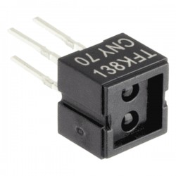
Refleksinis IR kliūties aptikimo jutiklis CNY70
0,76€
-
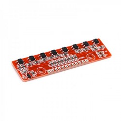
IR linijos sekimo modulis (8 kanalų) QTR-8A
9,00€
-
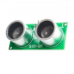
Ultragarsinis atstumo matavimo modulis US-015
3,15€
-
Refleksinis IR kliūties aptikimo jutiklis TCRT1000
3,97€
-
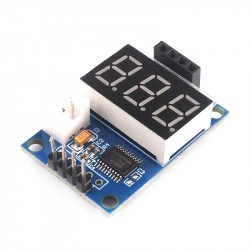
HC-SR04 atvaizdavimo modulis (ultragarsiniams jutikliams)
6,99€
-
Ultragarsinio jutiklio laikiklis mėlynas
2,36€
-
Ultragarsinio jutiklio laikiklis raudonas
2,36€
-
Ultragarsinio jutiklio laikiklis geltonas (žemesnis)
3,03€
-
Spalvos atpažinimo modulis su TCS3200 8pin
7,79€