Prekių nėra
(Kainos su PVM)
 Padidinti

Tik internetu
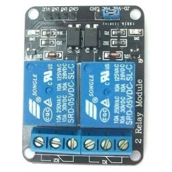
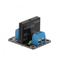
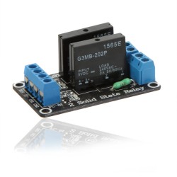
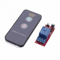
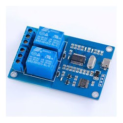
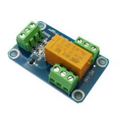
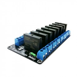
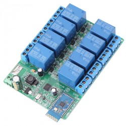
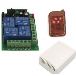
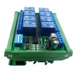
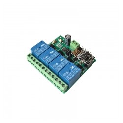
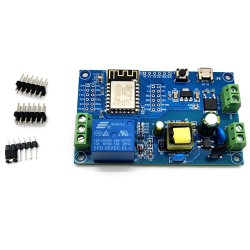
RS485 7-24V DC relės ir 3-30V įėjimo Modbus RTU modulis
d6710
Nauja prekė
Vieno kanalų relės ir vieno IN modulis valdomas per RS485/TTL UART komunikacijų sąsajas (Modbus). Gali veikti tiek 24V tiek žemesnės įtampos sistemose.
Prekių kiekis mūsų sandėlyje: 20
Charakteristikos
| Suderinama su Arduino™ ir *duino | Taip |
| Kanalų skaičius | 2 |
| Maksimali valdoma srovė | 10A kanalui |
| Maksimali valdoma įtampa | AC250V; DC30V |
| Būsenos indikacija | Taip. LED |
| Optinis atskyrimas | Taip |
| Nominali darbinė įtampa | 5V |
| Maitinimo įtampa | 7-30V DC |
| Skaitmeninių įėjimų/išėjimų skaičius | 1DO(SPDT) ir 1DI |
| Matmenys | 63 x 33 x 22 mm |
Apie prekę
Overview
LC 1-Way Modbus relay module equipped with mature and stable 8-bit MCU and RS485 level communication chip,adopt standard Modbus RTU format RS485 communication protocol,It can realize 1-Way optocoupler input signal detection and 1Way relay output, can be used for digital detection or power control occasions.
Function
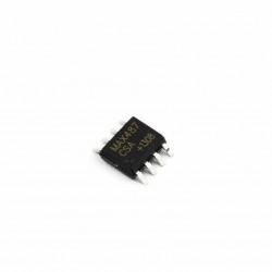
1. On-board mature and stable 8-Bit MCU and RS485 level communication chip.
2. Communication protocol: support standard Modbus RTU protocol
Communication interface: support RS485/TTL UART interface.
4. Communication baud rate: 4800/9600/19200, default 9600bps, Support power-down save.
5. Optocoupler input signal range, DC3.3-30V(this input not available for relay control).
6. Output signal: Relay switch signal, support manual control,flash OFF/ON mode,The delay base is 0.1S,the maximum allowable flash OFF/ON time is 0xFFFF*0.1S=65535*0.1S=6553.5S.
7. Device address:range:1-255,default 255,Support power-down save.
8. Baud rate/optocoupler input status/relay status/device address can be read by software/commands.
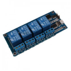
9. On-board 4-Way 5V,10A/250V AC 10A/30V DC relay,can continuously sucking 100,000 times, it has Diode flow protection for short response times.
10. On-board relay switch indicator.
11. Supply voltage: DC7-24V, support DC socket 5.08mm terminal power supply, with input anti-reverse protection.
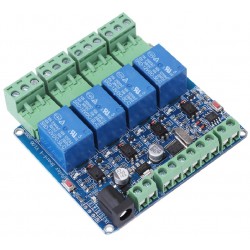
1. DC-005 Socket: DC7-24V power input socket
2. VCC, GND: DC7-24V power input terminal
3. DC3.3-30V Optocoupler signal input
IN1: Channel 1 positive
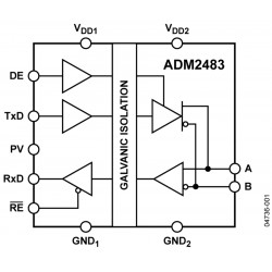
4. A+,B-: RS485 communication Interface, A+, B- are respectively connected to A+, B- of the external control terminal
5. Relay switch signal output
NC: Normally closed end ,the NC disconnect with COM when relay closed and connect with COM when relay released
COM: Common end
NO: Normally opened end,the NO disconnect with COM when relay released and connect with COM when relay closed
GND, RXD, TXD: TTL level UART communication Interface,GND,RXD,TXD separately connect to the external control terminal GND,TXD,RXD
Modbus RTU introduction of instruction
Modbus device through receive from external control terminal (like Host computer/MCU )Modbus RTU instruction to perform related operations, one frame instruction generally consists of device address, function code, register address, register data, and check code,frame length is related to function code. Each frame date’s first byte is the device address.can set range on 1-255 default 255(scilicet 0xFF),the last 2byte is CRC check code.
Suppose the device address is 255, the commonly used Modbus RTU instructions are as follows:
1.Turn on the relay No. 1 (manual mode)
Send: FF 05 00 00 FF 00 99 E4
Return: FF 05 00 00 FF 00 99 E4
Remarks:
(1)Send the 3--4th byte of the transmitted frame represents the relay address,the relay 1-relay 8 address are respectively 0x0000,0x0001,0x0002,0x0003,0x0004,0x0005,0x0006,0x0007.
(2)The 5--6th byte of the transmitted frame represents the data, 0xFF00 represent turn on relay,0x0000 represent turn off relay.
2.Turn off the relay No. 1 (manual mode)
Send: FF 05 00 00 00 00 D8 14
Return: FF 05 00 00 00 00 D8 14
5.Turn on all relay
Send: FF 0F 00 00 00 08 01 FF 30 1D
Return: FF 0F 00 00 00 08 41 D3
6.Turn off all relay
Send: FF 0F 00 00 00 08 01 00 70 5D
Return: FF 0F 00 00 00 08 41 D3
7.Set the device address to 1
Send: 00 10 00 00 00 01 02 00 01 6A 00
Return: 00 10 00 00 00 01 02 00 01 6A 00
Remark: The 9th byte of the transmitted frame,0x01 is the written device address.
8.Set the device address to 255
Send: 00 10 00 00 00 01 02 00 FF EB 80
Return: 00 10 00 00 00 01 02 00 FF EB 80
Remarks: The 9th byte of the transmitted frame, 0xFF is the written device address.
9.Read device address
Send: 00 03 00 00 00 01 85 DB
Return: 00 03 02 00 FF C5 C4
Remarks: The 5th byte of the Return frame, 0xFF is the read device address.
10.Read device address
Send: FF 01 00 00 00 08 28 12
Return: FF 01 01 01 A1 A0
Remarks: The 4th byte of the Return frame,the Bit0--Bit7 of 0x01 representing relay 1-relay 8, 0 is turn off .1 is turn on.
11.Read optocoupler input status
Send: FF 02 00 00 00 08 6C 12
Return: FF 02 01 01 51 A0
Remarks: The 4th byte of the Return frame, the Bit0--Bit7 of 0x01 represent input signal of optocoupler1- optocoupler 8, 0 represent low level ,1 represent high level
12.Set the baud rate to 4800
Send: FF 10 03 E9 00 01 02 00 02 4A 0C
Return: FF 10 03 E9 00 01 C5 A7
Remarks: The 9th byte of the transmitted frame is the baud rate setting value, 0x02, 0x03, 0x04 represents 4800, 9600, 19200
13.Set the baud rate to 9600
Send: FF 10 03 E9 00 01 02 00 03 8B CC
Return: FF 10 03 E9 00 01 C5 A7
14.Set the baud rate to 19200
Send: FF 10 03 E9 00 01 02 00 04 CA 0E
Return: FF 10 03 E9 00 01 C5 A7
15.Read the baud rate
Send: FF 03 03 E8 00 01 11 A4
Return: FF 03 02 00 04 90 53
Remarks: The 5th byte of the Return frame represent read baud rate, 0x02, 0x03, x04 represents 4800,9600,19200.
16.Turn on no.1 relay (flash off mode)
Send: FF 10 00 03 00 02 04 00 04 00 14 C5 9F
Return: FF 10 00 03 00 02 A4 16
Remarks:
(1)The 3-4th byte of the transmitted frame is represent relay address,relay1-relay8’s address separately is 0x0003,0x0008,0x000D,0x0012,0x0017,0x001C,0x0021,0x0026 .
(2)The 10th-11th byte of the transmitted frame represents the delay setting value, and the delay base is 0.1S, so the delay time is 0x0014*0.1=20*0.1S=2S, and the relay automatically turn off after turned on 2S
17.Turn off no.1 relay (flash off mode)
Send: FF 10 00 03 00 02 04 00 02 00 1E A5 99
Return: FF 10 00 03 00 02 A4 16
Remarks:
(1)The 3th-4th byte of the transmitted frame is represent relay address,relay1-relay8’s address separately is 0x0003,0x0008,0x000D,0x0012,0x0017,0x001C,0x0021,0x0026
(2)The 10th-11th byte of the transmitted frame represents the delay setting value, and the delay base is 0.1S, so the delay time is 0x001E*0.1=30*0.1S=3S
Atsiliepimai
Šiuo metu klientų atsiliepimų nėra.
Priedai
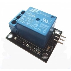
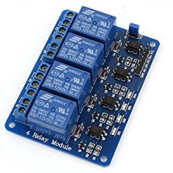
5V relės modulis
1,88€Relė SSR-25 DA
6,78€2 kanalų USB relių modulis
14,74€


30 kitos prekės toje pačioje kategorijoje:
-

433MHz nuotolinio valdymo pultelis su baterija
8,71€
-

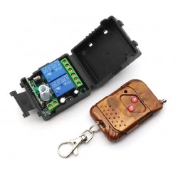
4 kanalų bevielė relė su 433MHz nuotolinio valdymo pulteliu (su bat.)
19,60€
-
8 kanalų Bluetooth relių modulis 5-12V
36,76€
-
RS485 4 kanalų 12V DC relių Modbus RTU modulis su STM8S103
24,18€
-
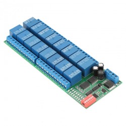
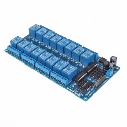
RS485 16 kanalų 12V DC relių Modbus RTU modulis
48,00€
-
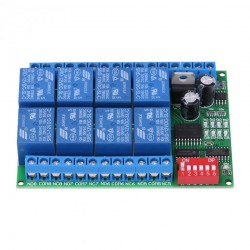
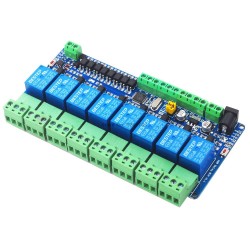
RS485 8 kanalų 12V DC relių Modbus RTU modulis
23,63€
-
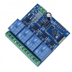
4 kanalų Bluetooth relių modulis 12V
22,20€
-
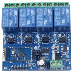
4 kanalų Bluetooth relių modulis 5V
22,20€
-
Bevielė dviguba relė KGS-B20 su nuotolinio valdymo pulteliu (315MHz)
13,92€
-
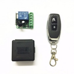
Bevielė relė su nuotolinio valdymo pulteliu 315MHz
11,95€
-

4 kanalų bevielė relė su 315MHz nuotolinio valdymo pulteliu (su bat.)
19,36€
-
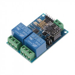
2 relių modulis su ESP8266 (WiFi)(5V)
17,71€
-
RS485 8 kanalų 12V DC 8DO ir 8DI Modbus RTU modulis su STM8S103
35,33€
-
4 kanalų bevielė relė su 433MHz nuotolinio valdymo pulteliu (su bat.)
19,36€
-

433MHz nuotolinio valdymo pultelis
8,47€
-

433MHz nuotolinio valdymo pultelis (apvalus su baterija)
8,99€
-

315MHz nuotolinio valdymo pultelis su baterija
8,71€
-

433MHz nuotolinio valdymo pultelis AK-079KB su baterija
8,35€
-
RS485 8 kanalų 12V DC relių Modbus RTU modulis su DIN laikikliu
32,67€
-
Bevielė relė su nuotolinio valdymo pulteliu (230VAC 433MHz)
15,13€
-

Bevielė relė su 433MHz nuotolinio valdymo pulteliu
11,95€
-
4 relių modulis su ESP8266 (WiFi)(5V)
28,06€
-
Relės modulis su ESP8266 (WiFi)(230VAC / 7-12VDC / USB)
23,96€
-

433MHz nuotolinio valdymo pultelis on/off su baterija
8,71€
-

433MHz nuotolinio valdymo pultelis su baterija
9,44€
-

3 mygtukų 433MHz nuotolinio valdymo pultelis su baterija
8,77€
-

4 mygtukų 433MHz nuotolinio valdymo pultelis su baterija
8,76€
-

433MHz nuotolinio valdymo pultelis on/off su baterija
8,71€
-

4 mygtukų 433MHz nuotolinio valdymo pultelis su baterija
8,23€
-

433MHz nuotolinio valdymo pultelis A/B su baterija
8,71€