Krepšelis 0 Prekė Prekės (tuščia)
Prekių nėra
Turi būti nustatyta Pristatymas
0,00€ PVM
0,00€ Iš viso mokėti
(Kainos su PVM)
Produktas sėkmingai pridėtas į pirkinių krepšelį
Kiekis
Iš viso mokėti
Krepšelyje yra 0 elementų. Krepšelyje yra 1 elementas.
Viso krepšelio vertė (su PVM)
Pakavimas ir pristatymas (su PVM) Turi būti nustatyta
Iš viso mokėti (su PVM)


Tik internetu
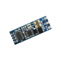
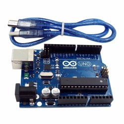
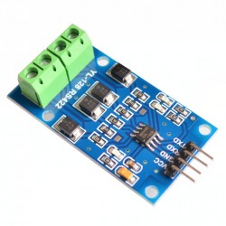
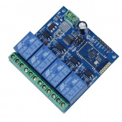
Uno išplėtimo shield'as V5 Xbee RS485
d0195
Nauja prekė
Naudojant šią išplėtimo plokštę lengviau prijungsite įvairius Arduino sistemos komponentus. Taip pat žymiai lengviau prijungsite populiariausius komunikacijų modulius. Tinka Arduino UNO, Mega, Duemilanove
Prekių kiekis mūsų sandėlyje: 3
Dėmesio: Paskutinės prekės!
Charakteristikos
| Suderinama su Arduino™ ir *duino | Taip |
| Jungties žingsnis | 2,54mm |
| Matmenys | 54 x 58 x 18 mm |
Apie prekę
Specification:
- RS485 Support
- Xbee (Xbee pro) Support
- Bluetooth Support
- APC220 Support
- SD card interface Support
- Xbee (Xbee pro) Support
- Bluetooth Support
- APC220 Support
- SD card interface Support
1. extension of 14 digital IO ports (12 servo interface) and power;
2. 6 analog IO ports and power;
3. 1 digital external power port terminal;
4. Digital-port external power supply and an onboard power supply automatic switching;
5. 1 External power input terminal and an input pin;
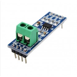
6. RS485 interface;
7. reset button;
8. xbee/Bluetooh Bee Bluetooth wireless data transmission interface;
9. APC220/Bluetooh V3 Bluetooth wireless data transmission interface;
10. IIC/I2C/TWI interface;
11. 3.3V output port;
12. SD card module interface;
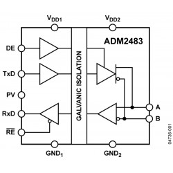
RS485:
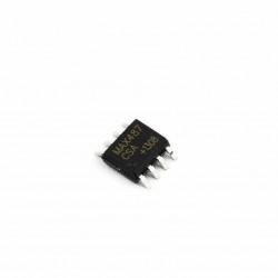
* It uses an SP485CN chip to handle comms.
* The screw terminals (assuming that the three jumpers are set to '485') marked 'A' and 'B' go directly to the IC 'A' and 'B' pins (6 & 7 respectively).
* The screw terminal marked VCC goes to the IC VCC pin (8), and also to the board's +5V line (i.e. the Arduino's +5V rail).
* The screw terminal marked GND goes to the IC GND pin (5), and also to the board's GND line (i.e. the Arduino's 0V rail).
* The chip's DI (Data Input?) pin (4) is connected to the Arduino's Digital Pin 1 (TX).
* The chip's RO (Data Output?) pin (1) is connected to the Arduino's Digital Pin 0 (RX), with a resistor pull-up to the +5V rail.
* The chip's DE (output enable) pin (3) is connected (via a resistor) to the Arduino's Digital Pin 2 - this is active high.
* This DE pin is also connected to the chip's RE bar (receiver enable) pin (2) and therefore controlled by the Arduino's Digital pin 2 too - this is active low.
* Arduino Digital Pin 2 = Rx/Tx 'Enable'; High to Transmit, Low to Receive
* So, to transmit data from Arduino Digital Pin 1 you need to take Digital pin 2 high, and to receive data to Arduino Digital Pin 0 you need to take Arduino Digital pin 2 low.
Sample Code:
RS485 Transmit Data
int EN = 2; //RS485 has a enable/disable pin to transmit or receive data. Arduino Digital Pin 2 = Rx/Tx 'Enable'; High to Transmit, Low to Receive
void setup()
{
pinMode(EN, OUTPUT);
Serial.begin(19200);
}
void loop()
{
// send data
digitalWrite(EN, HIGH);//Enable data transmit
Serial.print('A');
delay(1000);
}
RS485 Receiving Data
int ledPin = 13;
int EN = 2;
int val;
void setup()
{
pinMode(ledPin, OUTPUT);
pinMode(EN, OUTPUT);
Serial.begin(19200);
}
void loop()
{
// receive data
digitalWrite(EN, LOW);//Enable Receiving Data
val = Serial.read();
if (-1 != val) {
if ('A' == val) {
digitalWrite(ledPin, HIGH);
delay(500);
digitalWrite(ledPin, LOW);
delay(500);
}
}
}
Atsiliepimai
Šiuo metu klientų atsiliepimų nėra.
Priedai


30 kitos prekės toje pačioje kategorijoje:
-
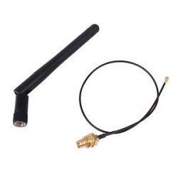
SMA antena (2,5dB) 2,4GHz
3,06€
-
SMA antena (16dBi) 2,4GHz
7,30€
-
Bluetooth (BT) bevielės komunikacijos modulis SPP-C su adapteriu
5,11€
-
2x 50W Bluetooth audio stiprintuvas (8-25V) su TDA7492P
19,36€
-
Variklių valdymo shield'as Fundumoto (2x H-bridge) su L298P su buzzer
13,92€
-
iBeacon Bluetooth švyturėlis su CC2541
22,02€
-
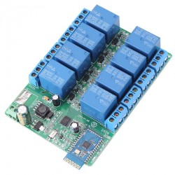
8 kanalų Bluetooth relių modulis 5-12V
36,76€
-
iBeacon Bluetooth švyturėlis su NRF51822
18,51€
-
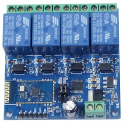
4 kanalų Bluetooth relių modulis 12V
22,20€
-
4 kanalų Bluetooth relių modulis 5V
22,20€
-
Bluetooth (BT) bevielės komunikacijos modulis HC-05
7,54€
-
Bluetooth (BT) bevielės komunikacijos modulis HC-06
6,93€
-
Bluetooth (BT) bevielės komunikacijos modulis AT-09 (HM-10)(CC2541) su adapteriu
6,78€
-
Bluetooth (BT) bevielės komunikacijos modulis AT-09 (HM-10)(CC2541)
6,85€
-
Bluetooth (BT) bevielės komunikacijos modulis SPP-C
5,32€
-
XY-BT-Mini Bluetooth 5.0 audio grotuvas
4,39€
-
2x 15W Bluetooth audio stiprintuvas su TPA3110 (8-26V)
11,25€
-
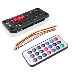
USB/microSD/FM/Line in/Bluetooth MP3 audio grotuvas
12,10€
-
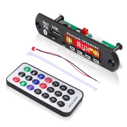
USB/microSD/FM/Line in/Bluetooth MP3, FLAC, WMA, APE audio grotuvas su garso...
12,10€
-
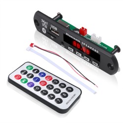
USB/microSD/FM/Line in/Bluetooth MP3, FLAC, WMA, APE audio grotuvas
10,89€
-
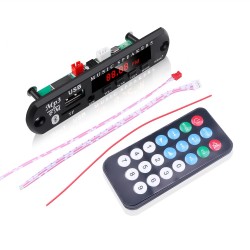
USB/microSD/FM/Line in/Bluetooth MP3 audio grotuvas
9,68€
-
2x50W Bluetooth 5.0 audio stiprintuvo modulis (5-27V) su TPA3116D2 su dangteliu
22,60€
-
USB/microSD/FM/Line in/Bluetooth MP3 audio grotuvas su 2x25W stiprintuvu ir...
15,73€
-
1x100W audio stiprintuvas (12-26V) su TPA3116D2
14,52€
-
2x120W audio stiprintuvas (12-26V) su TPA3116D2
9,68€
-
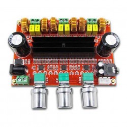
2x50W+1x100W 2.1 audio stiprintuvas (12-24V) su TPA3116D2
26,62€
-
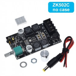
2x50W Bluetooth 5.0 audio stiprintuvas (5-27V) su TPA3116D2
21,42€
-
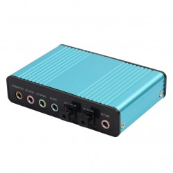
USB DAC (5.1/7.1, line in, mic in, optinis spdif in/out) AK103E
19,97€
-

WiFi bevielės komunikacijos modulis DT-06 su adapteriu
11,94€
-

XY-BT-Mini Bluetooth 5.0 audio grotuvas su USB TypeC
4,39€